EVK01
High Voltage, Fast Switching Isolated Buck DC-DC Converter Evaluation Board
EVK (Evaluation Kit)
Isolated Buck Converter
Available
FEATURES
- Isolated gate control using IZL-110
- Isolated 5V powered with NZL-300
- Fast 650V/3.5A GaN (from GaN Systems)
- Isolated output voltage readout using IZL-200
DESCRIPTION
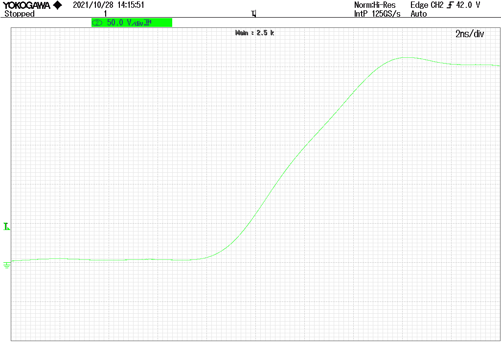
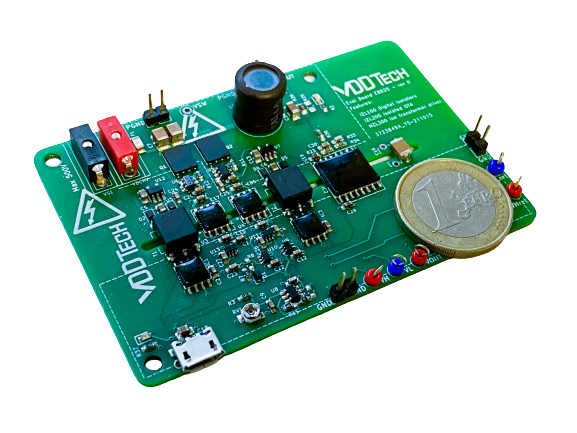
The EVK01 Evaluation Board is an open loop Buck converter designed to demonstrate VDDTECH’s product family capability in driving GaN power switches. EVK01 fast Buck features DVDT transitions faster than 70KV/µs.
OVERVIEW
A functional diagram of the EVK01 Evaluation Board is illustrated in the Figure 1. Each switch of the Buck is controlled through an IZL-110 digital isolator powered by a floating 5V isolated supply realized using the NZL-300. The open loop Buck converter is designed to output a voltage between 0 and 10V. The duty cycle being fixed, this makes the output voltage VOUT (0-10V) dependent of the input voltage VHV (0-300V). An IZL-200 allows to monitor the output voltage through the isolation.
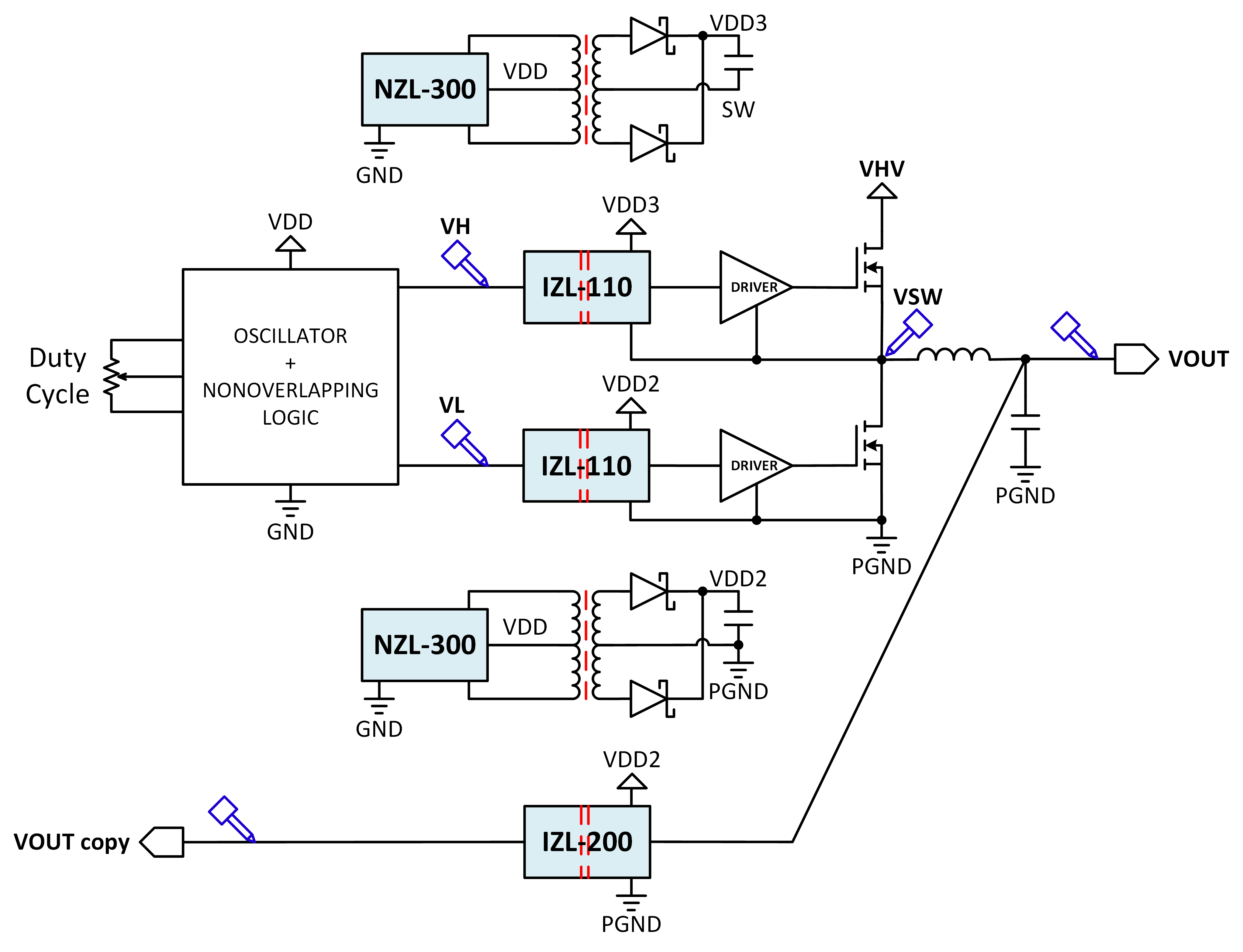
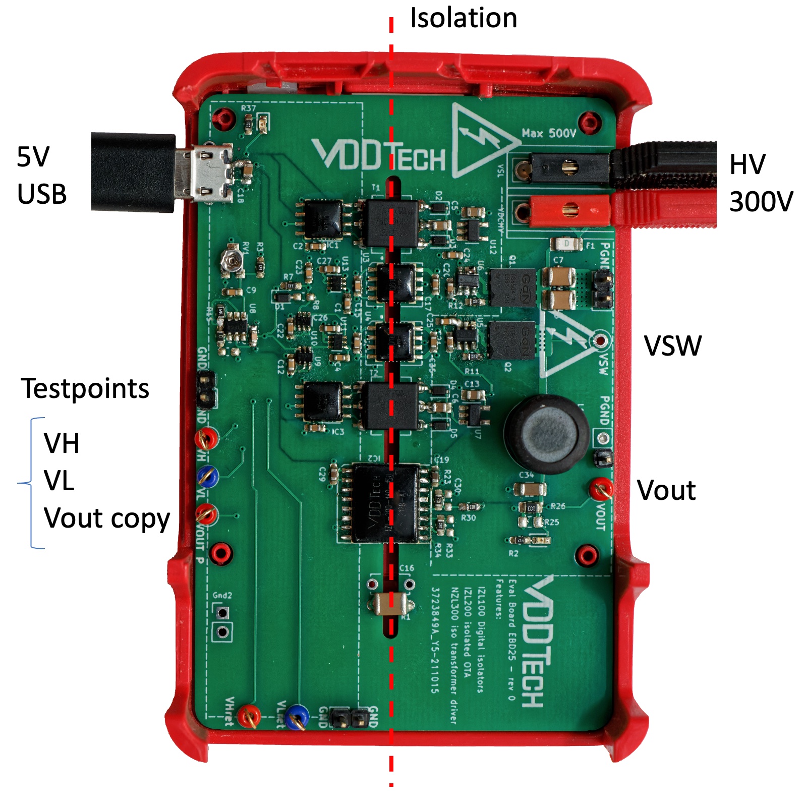
Figure 1: EVK01 Functional Block Diagram
| Interface | Connector | Description | |
|---|---|---|---|
| 1 | USB 5V | Female Micro-USB B-type | 5V power supply input. |
| 2 | HV | Female 2mm Banana Jacks | Input voltage range [0-300VDC]. Nominal input current <1mA. Current limit on voltage source should be inferior to 10mA. |
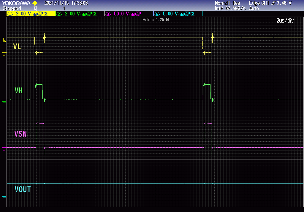
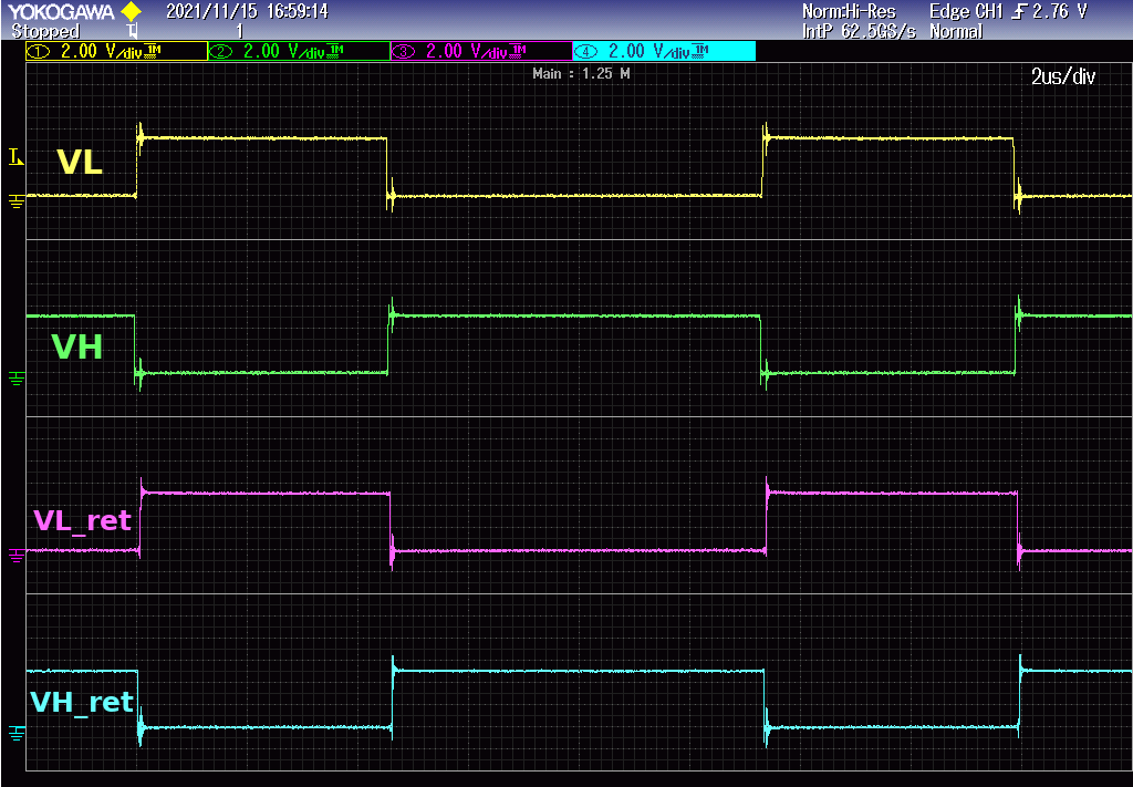
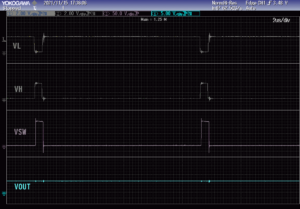
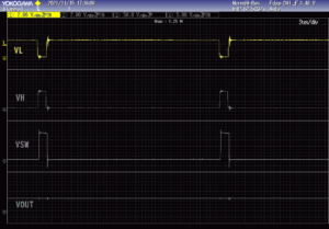
| 3 | VH | Test point | Provides an image of the high side gate drive voltage. Signal amplitude is 200mV on a 50Ω probe. typical frequency = 30kHz- 1% Duty-Cycle. |
| 4 | VL | Test point | Provides an image of the Low side Gate Drive voltage. Signal Amplitude is 200mV on a 50Ω probe. typical frequency = 30kHz- 98.5% Duty-Cycle. |
| 5 | VSW | Test point | Measuring access to switching node VSW for dV/dt measurement. |
Technical Documentation
Schematic file (link to pdf document)
PCB layout (link to pdf document)
Gerber files (link to zip archive)
Bill of materials BOM (open html document)
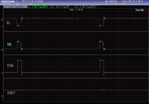
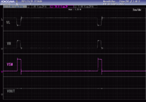
MEASUREMENTS